This tutorial shows how to replace the bottom gearbox on the XE-1
-
Remove Chain Guard
TOOLS REQUIRED
|
ID |
Description |
Task |
|
2.5 mm Hex Drive / Allen Key |
Loosen 8 Gauge Machine Screws |
1.1 Remove the five 8-Gauge Machine Screws that is used to attach the Chain Guard to the RH Rear Buoyancy. [Tools: 2.5 mm Hex Drive]

1.2 Remove the transparent acrylic Chain Guard over the RH Crank and Pedal.

|
|
INFORMATION: Do not use solvents to clean the Chain Guard. Use warm soapy water (dishwashing liquid soap) instead. |
2. Remove Rear RH Buoyancy (Cranks Fitted)
TOOLS REQUIRED
| ID | Description | Task |
| Long Nose Pliers | Remove Buoyancy Clips |
2.1 Remove all seven Buoyancy Clips. [Tools: Long Nose Pliers]
|
|
INFORMATION: Make a mental note of the positions where the Buoyancy Clips are removed. It is good practice to remove the white short Buoyancy Clip in front of the Seat Tube last. |
2.2 With the crank approximately in the 6 O’clock position, remove the Rear RH Buoyancy module over the Crank and Pedal.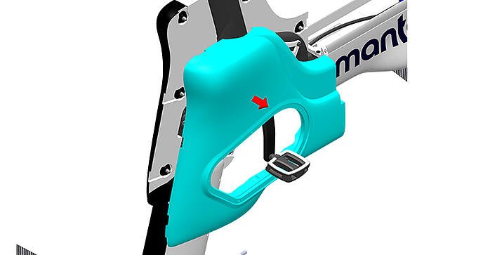
|
|
INFORMATION: The transparent Chain Guard must be removed before executing this step. It is possible to remove the RH Rear Buoyancy with the Chain Guard fitted and the RH Crank in the 5 O’clock position but this practice is not recommended as it could lead to component damage. |
3. Work Instruction - Remove Pedal Crank Arms LH and RH
TOOLS REQUIRED
| ID | Description | Task |
| Hex Key 8 mm | Remove Crank Bolts | |
| JP00025 | Park Tool Crank Extractor - CCP44 | Removing pedal cranks from motor spindle |
3.1 Remove Left-Hand Crank Arm 15mm ISIS Crank Bolt with a 8mm Hex Key.
|
|
INFORMATION: Rotate the Crank Bolt anti-clockwise (right-hand thread) to loosen. Take note of the LH or RH markings on the outside face near the pedal end of the Crank Arms. |

3.2 Remove Left-Hand Crank Arm with the Crank Extractor.

3.3 Remove Left-Hand Buoyancy Module

4. Work Instruction - Remove Chain.
TOOLS REQUIRED
| ID | Description | Task |
|
M5 Hex Key |
Loosen M6 Cap Screws |
4.1 Loosen the two M6 Cap screws securing the Chain Tensioner Bracket with Pulley (jockey wheel).
 |
INFORMATION: For the purpose of removing the Chain, only loosen the screws by one or two turns sufficient to release Chain tension. |
5. Work Instruction - Remove Chain Tensioner Bracket with Pulley
TOOLS REQUIRED
| ID | Description | Task |
| M5 Hex Key |
Loosen M6 Cap Screws |
5.1 Loosen and remove 35 mm Aluminium Cap Screws with large 18 mm Washers [M5 Hex]

|
INFORMATION: Note that Tef-Gel lubricant rather than Loctite thread locker is used on the screws in this location to allow for the screws to be loosened and fastened regularly when adjusting Chain tension. The M6 Chain Tensioner Bracket screws have a length of 35 mm and must not be replaced with shorter length screws. Using shorter screws may cause damage to the threads in the XE-1 Frame. |
5.2 Remove Chain Tensioner Bracket with Pulley Assembly

6. Work Instruction – Remove Drive Gear Assembly
TOOLS REQUIRED
| ID | Description | Task |
| M4 Hex Key | Remove M6 Countersink Head Screw |
6.1 Remove M6 Torque Plate Screw with countersink head and thread length 35 mm. [Tools: M4 Hex].
|
|
INFORMATION: Given that the aluminium screw with countersink head is driven with a M4 Hex, it is more likely for the screw head to get damaged than the rest of the M6 cap screws with M5 socket. Note that the screw can be removed in this scenario by drilling through the head of the screw with a 6 mm drill bit. This allows the bracket to be removed and the screw to be extracted using locking pliers (vice grips). |
 |
IMPORTANT: Do not use a shorter length screw (<35 mm) in this location. |
6.2 Remove the Drive Gear Assembly (includes Torque Plate and Sprocket) by pulling it off the Top Gearbox Input Shaft with spline.

|
|
INFORMATION: Following removal of the Drive Gear Assembly inspect the components.
|
7. Work Instruction - Remove the Strut Cowl with Cooling Hose
TOOLS REQUIRED
| ID | Description | Task |
| M 3 Hex Key | Loosen M4 Cap Screws |
7.1 Remove the seven M4 cap screws from the RH side of the Strut Cowling [Tools: M3 Hex]. 
|
|
INFORMATION : The seven M4 Nylock Nuts positioned in the hex shaped pockets on the LH Strut Cowling can fall out. Secure the nuts or remove and store them safely. |
7.2 Unlock the Strut Collar by rotating anti-clockwise through 70 degrees. Remove the Collar by sliding it forward over the Propeller Drive Shaft.
|
|
CAUTION: Do not use pliers to remove the Strut Cowling Collar as it may cause damage to the component. The Collar is easily rotated by hand and can be removed with little force. |
7.3 Pull the Cooling Hose backwards so that it is free from the Cooling Outlet Bracket.
7.4 With the screws and Strut Cowling Collar Removed, the two Strut Cowling halves (LH & RH) is held to each other only by being clipped together at the bottom trailing edge of the Strut Cowling. Unclip the RH Strut Cowling by pushing the Cowling Halves apart at the bottom of the trailing edge.
|
|
INFORMATION : The LH Strut Cowling is transparent in the image to show the mating boss feature of the clip on the RH Cowling. |
7.5 Remove the RH Strut Cowling and support the LH Strut Cowling as it is only held from falling by the Cooling Hose being routed through behind the Lower LH Motor Mount Bracket.
7.6 Pull the Cooling Hose out from behind the Lower LH Motor Mount Bracket and remove the LH Strut Cowling, exposing the Top and Bottom Gearboxes with Vertical Drive Shaft.

|
|
INFORMATION : Removal of the Strut Cowling provides access to the Top and Bottom Gearbox, Vertical Drive Shaft, Bayonet (Frame to Foil attachment) and Propeller Drive Shaft Assembly. |
8. Work Instruction - Remove Top Gearbox
TOOLS REQUIRED
| ID | Description | Task |
| M5 Hex Key | Loosen M5 Cap Screws | |
| 10 mm Open End or Combination Wrench | Loosen M6 Nylock Nuts |
8.1 Remove all three M6 Nylock Nuts and retrieve the flat M6 Washers. [Tools: 10 mm wrench, M5 Hex Drive]
8.2 Remove all three M6 X 30 mm Cap Screws, M6 Flat Washers and three Gearbox Mount Spacers (anodized black color) 
|
|
INFORMATION:Take note of the assembly sequence of the 3 cap screws holding the Top Gearbox: Screw, Washer, Bracket, Spacer, Gearbox, Washer, Nylock Nut. |
8.3 Remove the Top Gearbox by holding down the Vertical Drive Shaft lifting the Top Gearbox while gently pushing to the right to clear the Bottom LH Motor Mount Bracket.
9. Work Instruction - Remove vertical drive shaft
TOOLS REQUIRED
| ID | Description | Task |
| N/A | N/A |
9.1 To remove the Vertical Drive Shaft, simply pull it upwards to release from the Bottom Gearbox Input Shaft.
10. Work Instruction - Remove Bottom Gearbox
TOOLS REQUIRED
| ID | Description | Task |
| 5 mm Hex Drive / Allen Key | Loosen M6 Cap Screws | |
| 10 mm Open / Combination Wrench | Loosen M6 Nylock Nut |
10.1 Loosen and remove the two aft M6 nylock nuts. [Tools: 10 mm Wrench, 5 mm Hex Key]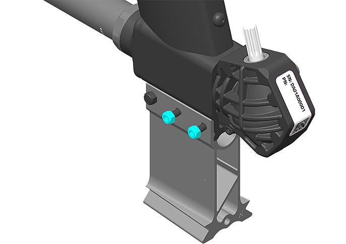
10.2 Remove the two aft 45 mm length cap screws that lock in the Bottom Gearbox. [Tools: By Hand]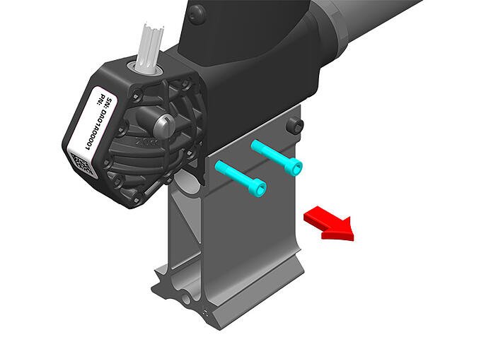
10.3 Remove the Bottom Gearbox from the Frame and disengage the Bottom Gearbox Input Shaft from the Propeller Drive Shaft.
|
|
INFORMATION: Inspect the Gearbox. If excessive wear and/or damage is detected, it is strongly recommended that the Propeller Drive Shaft Assembly is also removed and inspected. |
11. Work Instruction - Fit Bottom Gearbox
TOOLS REQUIRED
| ID | Description | Task |
|
5 mm Hex Drive /Allen Key |
Fasten M6 Cap Screws |
|
|
10 mm Open / Combination Wrench |
Fasten M6 Nylock Nut |
|
|
Torque Wrench (1 – 15 Nm range) |
Fasten M6 Nylock Nuts |
|
|
10 mm Socket |
Fasten M6 Nylock Nuts |
11.1 Fit the replacement Bottom Gearbox to the Frame and engage the Bottom Gearbox Input Shaft to the Propeller Drive Shaft. Rotate the Propeller Drive Shaft until the splines align. [Tools: By Hand Only]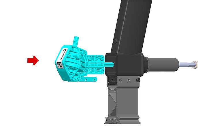
11.2 Fit the two aft 45 mm length cap screws through the Bayonet Upright and Bottom Gearbox Bracket from the right-hand side. [Tools: By Hand] 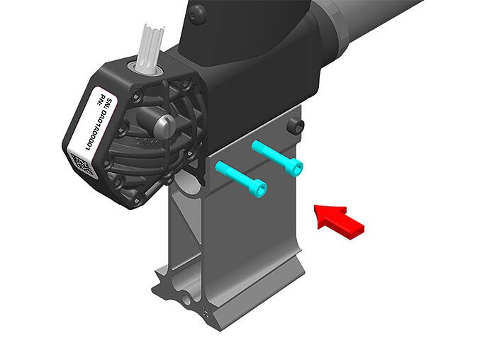
11.3 Fit the two aft M6 nylock nuts and fasten to a Torque value of 5 Nm. [Tools: Torque Wrench with 10 mm socket, 10 mm Wrench].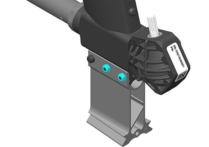
|
|
INFORMATION: If a Torque Wrench is not used, be careful not to over tighten the Nylock Nuts. Given the nylon locking seal, the nuts are not likely to come loose once fastened. |
12. Work Instruction - Fit Vertical Drive Shaft
TOOLS REQUIRED
| ID | Description | Task |
| N/A | N/A |
|
|
INFORMATION: Before fitting the Vertical Drive Shaft, inspect both ends to ensure the Drive Shaft Bushes are fitted and not damaged or worn. Both ends have the same geometry and it does not matter which end is positioned top or bottom. To minimize risk of damage, only fit the Vertical Drive Shaft if the Top Gearbox is available and is to be fitted immediately after. |
12.1 To fit the Vertical Drive Shaft, align one end with the splined input shaft of the Bottom Gearbox and slide it onto the shaft. [Tools: By Hand Only]
13. Fit Top Gearbox
(content coming soon)
Do not fully fasten
14. Fit Drive Gear Assembly
TOOLS REQUIRED
| ID | Description | Task |
|
Tef-Gel |
Assemble Drive Gear Assembly to Top Gearbox Input Shaft |
|
|
M4 Hex Key |
Fit M6 Torque Plate Countersink Head Screw |
|
|
Loctite 243 Thread Locking Compound |
Fit M6 Torque Plate Countersink Head Screw |
|
|
Torque Wrench |
Fasten M6 Torque Plate Countersink Head Screw |
14.1 Apply Tef-Gel (or equivalent lubricant) to the Top Gearbox Input Shaft. Insert the Drive Gear Assembly with the Sprocket internal spline fitting onto the external spline of the Top Gearbox Input Shaft.

14.2 Apply Loctite 243 (or equivalent thread locker) to the thread and assemble the M6 Torque Plate Screw through the Torque Plate and Lower Right-Hand Motor Mount to engage with the threaded boss on the Frame. Fasten to 5 Nm. [Tools: M4 Hex, Torque Wrench]
|
|
INFORMATION: The M6 Torque Plate Screw has a countersink head and thread length 35mm. Do not exchange for a shorter length screw. |
15. Fit Chain Tensioner Bracket with Pulley (Jockey Wheel)
TOOLS & JIGS REQUIRED
| ID | Description | Task |
|
M5 Hex Key |
Fasten M6 Cap Screw |
15.1 Position the Bracket with Pulley so that the screw holes align.

15.2 Apply Tef-Gel (not Loctite) to the threads and Insert the M6 x 35mm Cap Screws with 18 mm OD washers. Do not fasten fully to allow for Chain tension adjustment in a following step.
|
|
INFORMATION:
|
15.3 Torque fasteners to 5 Nm. Torque Plate then top gearbox
1xxx. Work Instruction - Fit Chain.
TOOLS REQUIRED
| ID | Description | Task |
|
M5 Hex Key |
Loosen M6 Cap Screws |
17.1 Prepare to fit the chain by setting up the chain tensioner assembly by loosening the pivot point screw (highlighted red) and chain tension locking screw (highlighted green) so that the Chain Tensioner Assembly can be moved freely up and down.
|
INFORMATION: The Chain Tensioner Assembly with Pulley (Jockey wheel) pivots around one screw serving as an axis (highlighted in red). The adjustment range is constrained by the slot and once adjusted the assembly is secured by firstly fastening the chain tension locking screw (highlighted in green) and finally the pivot screw. Do not use Loctite thread locker to the threads of the Chain Tensioner screws but use a lubricant like Tef-Gel (or equivalent) lubricant. |
17.2 With the Chain Tensioner Assembly raised, fit the chain over the 16T Drive Gear Sprocket and 42T Chainring.
17.3 Apply light pressure (about 1kg of force) to the top of the Chain Tensioner Bracket and fasten the chain tension locking screw positioned in the slot at the same time.
17.4 Check Chain tension by moving the Chain up and down just above the Chain Tensioner Assembly in the center of the span between Chainring and Drive Gear Sprocket. 8-10 mm of play is ideal.
|
INFORMATION: If Chain tension is too low, it is more likely that the Chain will fall off during use. With the Chain Tension too high the Pulley (jockey wheel) M5 Bolt may fail and the Jockey Wheel (pulley) to break off and drive to be lost. It is normal to observe slight variation in Chain tension as the Chainring gear is rotated. Rotate the Chainring gear through 360 degrees and ensure that the Chain is not excessively tight (< 8 mm of play) at any point |
18. Fit Strut Cowling with Cooling Hose
TOOLS REQUIRED
|
ID |
Description |
Task |
|
Hex Key 3 mm |
M4 Cap Screws |
18.1 Thread the Cooling Hose through the cowling cut out and behind the Bottom LH Motor Mount Bracket. Position the LH Strut Cowling with features aligning with Propeller Drive Shaft Hub, Bottom Gearbox and Frame.

18.2 Position the RH Strut Cowling to align with the LH Strut Cowling. Gently push the bottom of the trailing edges of the two cowling halves together until you hear a clicking sound as the trailing edges interlock.

18.3 With the two internal molded locking boss features of the Prop Collar facing the Strut Cowling and aligned in the 11 & 5 o’clock position, push the Prop Collar into place while holding the two Strut Cowling halves together.

18.4 Rotate the Prop Collar clockwise (by hand only) through approximately 70 degrees until the lock stop is reached.

18.5 With the M4 Nylock Nuts held in the nut pockets of the LH Strut Cowling, fix the two Strut Cowling halves in place by fitting and fastening the seven M4X20 stainless steel cap screws to a torque value of 2.5 to 3 Nm. [Tools: M3 Hex Drive].

18.6 Push the Cooling Hose into the Cooling Hose Bracket and check that the hose is free of any obstruction that may prevent the free flow of cooling water onto the motor.

19. Work Instruction – Fit Rear Buoyancy
19.1 Position and hold Left-Hand Rear Buoyancy Module.

20. Fit Rear RH Buoyancy (Cranks Fitted)
TOOLS REQUIRED
| ID | Description | Task |
| Long Nose Pliers | Fit Buoyancy Clips |
20.1 With the Crank approximately in the 6 O’clock position, position the Rear RH Buoyancy Module by sliding it over the top of the RH Pedal and Crank. 
|
|
INFORMATION: If the RH Cranks is fitted, the Chain Guard must be removed before fitting the Rear RH Buoyancy to the bike. |
20.2 Align the Rear RH Buoyancy with the Frame and LH Buoyancy so that the Insert Locating Pins align with the mating inserts on the RH Buoyancy module.

20.3 Fit all seven Buoyancy Clips to secure both LH and RH Buoyancy halves to the hydrofoiler. [Tools: Long Nose Pliers]
21. Fit LH Crank with pedal
(content coming soon)