This tutorial shows how to replace the Motor & cable assembly from the XE-1
1. Remove propeller assembly (for Safety reasons only)
TOOLS REQUIRED
| ID | Description | Task |
| N/A | 17 mm Open Wrench | Loosen M10 Nylock Nut |
1.1 While holding the Propeller to stop it from rotating, loosen and remove the Nose Cone by rotating it anti-clockwise. [Tools: By Hand Only].

1.2 Loosen and remove the stainless steel M10 nylock nut with washer.

1.3 Remove the Propeller with Hex Block by pulling it forward off the end of the Propeller Drive Shaft.

1.4 With the Propeller removed, it is recommended to store the nut and washer on the end of the Drive Shaft, improving safety by creating a blunt end. Tighten by hand only to engage the nylon locking seal and prevent the nut from being lost.

1. Work Instruction – Remove Front Buoyancy
TOOLS REQUIRED
| ID | Description | Task |
| N/A | Long Nose Pliers | Remove Buoyancy Clips |
1. Remove all 5 Buoyancy Clips that lock the two halves together using Long Nose Pliers.

|
|
INFORMATION: The Battery Tray can remain in place during this procedure. |
1.2 Locate the Stirrup underneath the Battery Tray positioned just forward of the Rear Buoyancy. Reach past the Motor Power Cable and slide the Stirrup (highlighted in the image) forward to the end of the slot. This will unlock the Front Buoyancy from the Battery Tray for removal.

|
|
INFORMATION: Even with the Stirrup in the forward (unlocked) position, the Front Buoyancy halves should not drop but do take care not to accidentally drop the two Buoyancy halves during this and following steps. |
1.3 To remove the Right-Hand Front Buoyancy set apply pressure just below the front of the Battery Tray and push the Buoyancy set downwards to release from the Battery Tray. The RH Buoyancy module can now be removed.

1.4 To remove the Right-Hand Front Buoyancy set apply pressure just below the front of the Battery Tray and push the Buoyancy set downwards to release from the Battery Tray. The Right-Hand Front Buoyancy module can now be removed.

|
|
INFORMATION: Pay attention to the technique and sequence when removing the Front Buoyancy set. Re-fitting the Front Buoyancy requires the same process to be executed in reverse. |
1. Work Instruction – Remove Battery Tray
TOOLS REQUIRED
| ID | Description | Task |
| N/A | M4 Hex Key | Remove M6 Countersink Head Screws from Battery Latches |
1.1 Loosen and remove the M6 countersink head screws with a M4 Hex Key.

1.2 Remove the Battery Latches. The Set Screws can remain in place if the Battery Latches are to be re-used.

1.3 Remove the Battery Tray. The Connector Assembly Plug can fit through the matching shape in the battery tray slot to release the Battery Tray.

|
|
INFORMATION: The cable with Connector Assembly Plug is permanently attached to the Motor and is not removed in this step. |
1.4 The Stirrup can now be removed from the Frame if required.

1. Work Instruction - Remove Pedal Crank Arms LH and RH
TOOLS REQUIRED
| ID | Description | Task |
| Hex Key 8 mm | Remove Crank Bolts | |
| JP00025 | Park Tool Crank Extractor - CCP44 | Removing pedal cranks from motor spindle |
1.1 Remove Left-Hand Crank Arm 15mm ISIS Crank Bolt with a 8mm Hex Key.
1.2 Remove Left-Hand Crank Arm with the Crank Extractor.
|
|
INFORMATION: Rotate the Crank Bolt anti-clockwise (right-hand thread) to loosen. Take note of the LH or RH markings on the outside face near the pedal end of the Crank Arms. |
1.3 Remove Right-Hand (RH) Crank Arm15mm ISIS Crank Bolt with a 8mm Hex Key.

1.4 Remove Right-Hand (RH) Crank Arm with the Crank Extractor.

1. Remove the Left-Hand and Right-Hand Rear Buoyancy Modules
TOOLS & JIGS REQUIRED
| ID | Description | Task |
| Long nose pliers | Remove Buoyancy Clips |
1.1 Remove (pull out) the seven Buoyancy Clips holding the Rear Buoyancy halves together. [Tools: Long Nose Pliers]


|
INFORMATION: With the Cranks and Buoyancy Clips removed both Left-Hand and Right-Hand Buoyancy Modules are free and can be removed. Take care not to drop the Rear Buoyancy halves when pulling out the last clip. Dropping the Buoyancy parts may cause scratches and or other damage. Leaving the Clip in front of the seat tube to be removed last is recommended. |
1.2 Remove Right-Hand Buoyancy Module

1.3 Remove Left-Hand Buoyancy Module

1. Remove Chain.
TOOLS REQUIRED
| ID | Description | Task |
| N/A |
M5 Hex Key |
Loosen M6 Cap Screws |
1.1 Loosen the two M6 Cap screws securing the Chain Tensioner Bracket with Pulley (jockey wheel).
|
INFORMATION: For the purpose of removing the Chain, only loosen the screws by one or two turns sufficient to release Chain tension. |
1.2 Push the Chain Tensioner Assembly upwards clear from the Chain.
1.3 Remove the Chain.
|
INFORMATION: The Chain is easily removed by derailing it from the Chainring by slowly rotating the Chainring gear while pushing the Chain to the side |
1. Remove Drive Gear Assembly
TOOLS REQUIRED
| ID | Description | Task |
| M4 Hex Key | Remove M6 Countersink Head Screw |
1.1 Remove M6 Torque Plate Screw with countersink head and thread length 35 mm. [Tools: M4 Hex].

|
|
INFORMATION: Given that the aluminium screw with countersink head is driven with a M4 Hex, it is more likely for the screw head to get damaged than the rest of the M6 cap screws with M5 socket. Note that the screw can be removed in this scenario by drilling through the head of the screw with a 6 mm drill bit. This allows the bracket to be removed and the screw to be extracted using locking pliers (vice grips). |
 |
IMPORTANT: Do not use a shorter length screw (<35 mm) in this location. |
1.2 Remove the Drive Gear Assembly (includes Torque Plate and Sprocket) by pulling it off the Top Gearbox Input Shaft with spline.

|
|
INFORMATION: Following removal of the Drive Gear Assembly inspect the components.
|
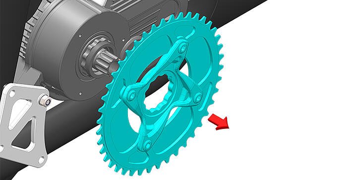
1. Remove Chain Ring
TOOLS REQUIRED
| ID | Description | Task |
| JP00060 | TOOL, LOCKING RING, ISIS, WITH CORE, STD | Remove Chain Ring Spider Lock Nut (Ring) |
| 19 mm Ring or Open-Ended Wrench | Remove Chain Ring Spider Lock Nut (Ring) |
1.1 Loosen and remove the Lock Nut by rotating the round nut clockwise with the Locking Ring tool.
|
|
INFORMATION: Screw the tool core into the axle, place the main tool body with pins over the core and to engage the 8 Lock Nut holes. Using a 19 mm wrench, rotate the tool and nut clockwise to remove the lock nut. Use a long chain whip to hold the chain ring from rotating on the free spinning motor hub when loosening the Lock Nut. |

1.2 Remove the Chain Ring Assembly by pulling off the Motor Drive Shaft Spline.
1. Work Instruction - Fit Chain.
TOOLS REQUIRED
| ID | Description | Task |
|
M5 Hex Key |
Loosen M6 Cap Screws |
1.1 Prepare to fit the chain by setting up the chain tensioner assembly by loosening the pivot point screw (highlighted red) and chain tension locking screw (highlighted green) so that the Chain Tensioner Assembly can be moved freely up and down.
|
INFORMATION: The Chain Tensioner Assembly with Pulley (Jockey wheel) pivots around one screw serving as an axis (highlighted in red). The adjustment range is constrained by the slot and once adjusted the assembly is secured by firstly fastening the chain tension locking screw (highlighted in green) and finally the pivot screw. Do not use Loctite thread locker to the threads of the Chain Tensioner screws but use a lubricant like Tef-Gel (or equivalent) lubricant. |
1.2 With the Chain Tensioner Assembly raised, fit the chain over the 16T Drive Gear Sprocket and 42T Chainring.
1.3 Apply light pressure (about 1kg of force) to the top of the Chain Tensioner Bracket and fasten the chain tension locking screw positioned in the slot at the same time.
1.4 Check Chain tension by moving the Chain up and down just above the Chain Tensioner Assembly in the center of the span between Chainring and Drive Gear Sprocket. 8-10 mm of play is ideal.
|
INFORMATION: If Chain tension is too low, it is more likely that the Chain will fall off during use. With the Chain Tension too high the Pulley (jockey wheel) M5 Bolt may fail and the Jockey Wheel (pulley) to break off and drive to be lost. It is normal to observe slight variation in Chain tension as the Chainring gear is rotated. Rotate the Chainring gear through 360 degrees and ensure that the Chain is not excessively tight (< 8 mm of play) at any point |
1. Remove RH Lower Motor Mount Bracket
TOOLS REQUIRED
| ID | Description | Task |
|
M5 Hex Key |
Loosen M6 Cap Screws |
|
|
10 MM Open/Combination Wrench |
Loosen M6 Nylock Nut |
1.1 Remove the M6 x 25 mm Cap Screw with M6 Washer from the RH Lower Motor Mount Bracket.
1.2 Remove the M6 Stainless Steel Nylock Nut, Stainless Steel Washer and short Nylon Sleeve (bush with shoulder), from the 70 mm length M6 Stainless Steel Cap Screw.
1.3 Remove the RH Lower Motor Mount Bracket.
1.4 Remove the Motor Mount Spacer.
1. Remove Motor and Cable Assembly.
TOOLS REQUIRED
| ID | Description | Task |
|
M5 Hex Key |
Loosen M6 Cap Screws |
|
|
10 MM Open/Combination Wrench |
Loosen M6 Nylock Nut |
1.1 Remove Lower Motor Mount 70 mm SS screw with Long Sleeve, Short Sleeve with Shoulder and Stainless Steel Washer.
|
INFORMATION: The Motor Mount Spacer (Anodized Red) will be removed in a later step. |
1.2 Loosen the M6 Top Motor Mount Stainless Steel Nylock Nuts by two full turns but do not remove.
1.3 Remove the Bottom LH Motor Mount Spacer (Anodized Red).
1.4 Pull the Motor Cooling Hose free from the Cooling Outlet Bracket.
1.5 First loosen all four, then remove the four M6 Aluminium Top Motor Mount Screws with Washers from Frame.
1.6 Remove the Motor with Top Motor Mount Brackets and Cable from the Frame.
1.7 Disassemble the Top Motor Mount Assembly and transfer the Brackets, Spacers, Water Cooling Outlet Bracket (also serving as a spacer) to the replacement Motor.
|
INFORMATION: The Motor Cable is not designed to be transferable from one Motor to the next. |
1. Work Instruction - Fit Motor and Cable Assembly.
TOOLS REQUIRED
| ID | Description | Task |
|
M5 Hex Key |
Fasten M6 Cap Screws |
|
|
10 MM Open/Combination Wrench |
Fasten M6 Nylock Nut | |
|
HP00162 |
LOCTITE 242 |
Fasten M6 Cap Screw to Frame |
|
INFORMATION: Read all information and refer to the supplied image for each step of the process before you proceed. |
1.1 If not already done, transfer then loosely assemble Top Motor Mount Brackets with Water Cooling Outlet Bracket in the left aft position.

|
INFORMATION: The brackets are fitted with the short side at the front and the taller side at the rear. |
1.2 Position the Motor & Cable Assembly in the Frame with the Cable facing forward passing on the left-hand side of the frame.
1.3 Apply Loctite 242 thread locker to the screw threads and loosely fit the four M6 Top Motor Mount Cap Screws with Washers to the Frame.
|
INFORMATION: To ensure alignment of the Drive Drain, the Top Motor Mount fasteners will be fastened later when both the LH and RH Lower Motor Mount Brackets are in place. |
1.4 Position and hold the LH Lower Motor Mount Spacer (Anodized Red) between the Lower LH Motor Mount and Lower Motor Mount with the cooling hose passing behind the spacer.
1.5 Fit the Lower Motor Mount Screw (70 mm length M6 Stainless Steel) with SS washer. Sleeve with shoulder and Long Sleeve through the Lower Left-Hand Motor Mount bracket, Motor Mount Spacer and Lower Motor Mount.
|
INFORMATION: Ensure that the screw is pushed in all the way so that the end of the long sleeve appear on the right-hand side. |
1.6 Insert the end of the Water Cooling Hose through the hole in the Water Cooling Bracket so that it makes contact with the Motor Cooling Fins.
1.7 Position a Motor Mount Spacer (anodized red color) onto the Lower Motor Mount Screw over the end of the Long Sleeve.
1.8 Fit the Lower Right-Hand Motor Mount Bracket with the curved side facing forward ensuring that the bracket holes align with that of the frame.
1.9 Loosely fit the Short Nylon Sleeve (with shoulder), M6 Stainless Steel Washer and M6 Stainless Steel Nylock Nut to the end of the Motor Mount Screw.
1.10 Apply Loctite, and loosely fit the M6 Aluminium Cap Screw and Washer to the bottom hole position of the Lower RH Motor Mount Bracket.
1.11 Temporarily fit two M6 screws loosely into the remaining hole positions to ensure alignment of the components.
1.12 With place holder screws loosely fitted in, fasten all motor mount fasteners to a torque value of 5 Nm.
1.13 Remove the two screws that were temporarily fitted to assist with alignment of the Lower RH Motor Mount Bracket.
1. Fit Drive Gear Assembly
TOOLS REQUIRED
| ID | Description | Task |
|
Tef-Gel |
Assemble Drive Gear Assembly to Top Gearbox Input Shaft |
|
|
M4 Hex Key |
Fit M6 Torque Plate Countersink Head Screw |
|
|
Loctite 243 Thread Locking Compound |
Fit M6 Torque Plate Countersink Head Screw |
|
|
Torque Wrench |
Fasten M6 Torque Plate Countersink Head Screw |
1.1 Apply Tef-Gel (or equivalent lubricant) to the Top Gearbox Input Shaft. Insert the Drive Gear Assembly with the Sprocket internal spline fitting onto the external spline of the Top Gearbox Input Shaft.

1.2 Apply Loctite 243 (or equivalent thread locker) to the thread and assemble the M6 Torque Plate Screw through the Torque Plate and Lower Right-Hand Motor Mount to engage with the threaded boss on the Frame. Fasten to 5 Nm. [Tools: M4 Hex, Torque Wrench]
|
|
INFORMATION: The M6 Torque Plate Screw has a countersink head and thread length 35mm. Do not exchange for a shorter length screw. |
1. Fit Chain Tensioner Bracket with Pulley
TOOLS & JIGS REQUIRED
| ID | Description | Task |
|
M5 Hex Key |
Fasten M6 Cap Screw |
1.1 Position the Bracket with Pulley so that the screw holes align.

1.2 Apply Tef-Gel (not Loctite) to the threads and Insert the M6 x 35mm Cap Screws with 18 mm OD washers. Do not fasten fully to allow for Chain tension adjustment in a following step.
|
|
INFORMATION:
|
1. Fit Chain Ring Assembly
TOOLS REQUIRED
| ID | Description | Task |
| JP00060 | TOOL, LOCKING RING, ISIS, WITH CORE, STD | Remove Chain Ring Spider Lock Nut (Ring) |
| 19 mm Ring or Open-Ended Wrench | Remove Chain Ring Spider Lock Nut (Ring) | |
| Generic round bar or Cassette Removal Tool with long chain whip. | Hold Chain Ring to prevent it from rotating when tightening Chain Ring Spider Lock Nut |
|
|
INFORMATION: Inspect the Chain Ring for excessive wear. For the Chain Ring, Chain, and Sprocket to work well together all components must have a similar pitch (state of wear). |
1.1 Place the Chain Ring Assembly onto the Motor Drive Shaft Spline.

1.2 Place the Lock Nut onto the Motor Drive Shaft and fasten by rotating the round Lock Nut anti-clockwise. [Tools: TOOL, LOCKING RING, ISIS, WITH CORE, STD].
|
|
INFORMATION: Screw the tool core into the axle, place the main tool body with pins over the core and to engage the 8 Lock Nut holes. Using a 19 mm wrench, rotate the tool and Lock Nut anti-clockwise to fasten. Use a round bar or Cassette Removal Tool with long chain whip to stop the Chain Ring from spinning while tightening. |
1. Fit Rear Buoyancy
1.1 Position and hold Left-Hand Rear Buoyancy Module.

1.2 Position and hold Right-Hand Rear Buoyancy Module.

|
INFORMATION: As soon as the two Rear Buoyancy halves are in position, insert one of the Buoyancy Clips (white clip in front of the Seat Tube is a good option) so that the assembly is self-supported. |
1.3 Insert all seven Buoyancy Clips (4 short white, 1 short black, 2 long black) to complete the assembly.
|
INFORMATION: Corresponding with the black and white colours of the Rear Buoyancy, four short white clips are fitted around the front, two long black clips at the rear and one short black clip is fitted on top behind the Seat Tube Clamp. |
1. Fit Pedal Crank Arms LH and RH
TOOLS REQUIRED
| ID | Description | Task |
| Hex Key 8 mm | Remove Crank Bolts | |
| Torque Wrench (20 – 60 Nm) | Fasten Crank Bolts (50 Nm) | |
| Rubber Mallet | Assemble Crank Arms to Motor Drive Shaft Spline |
1.1 Assemble RH Crank Arm to Motor Drive Shaft Spline and secure with 15 mm Crank Bolt. [Tools: Rubber Mallet, 8 mm Hex, Torque Wrench set to 50 Nm]
|
|
INFORMATION: Fit the Right-Hand Crank Arm (marked RH on outside face adjacent to Pedal thread) to the Drive shaft Spline and tap it firmly into place using a small head rubber mallet without making contact with buoyancy components. The Crank Bolt must progress at least two full turns without tension before tightening. Fastening the Crank Bolt with only one thread engaged can strip the thread from the Crank Bolt in which case it must be replaced. |
1.2 Fit a 15 mm ISIS Crank Bolt through the Right-Hand Crank to engage the internal thread of the Motor Drive Shaft. [Tools: 8 mm Hex, Torque Wrench]

|
|
INFORMATION: Use the Torque Wrench set to 50 Nm and fasten to the pre-set torque level. Rotate the Crank Bolt clockwise (right-hand thread) to fasten. |
1.3 Assemble Left-Hand Crank Arm to Motor Drive Shaft Spline and secure with 15 mm Crank Bolt. [Tools: Rubber Mallet, 8 mm Hex, Torque Wrench set to 50 Nm]
|
|
INFORMATION: Fit the Left-Hand Crank Arm (marked LH on outside face adjacent to Pedal thread) to the Drive shaft Spline and tap it firmly into place using a small head rubber mallet without making contact with buoyancy components. The Crank Bolt must progress at least two full turns without tension before tightening. Fastening the Crank Bolt with only one thread engaged can strip the thread from the Crank Bolt in which case it must be replaced. |
1.4 Fit a 15 mm ISIS Crank Bolt through the Left-Hand Crank to engage the internal thread of the Motor rive Shaft. [Tools: 8 mm Hex, Torque Wrench]
|
|
INFORMATION: Use the Torque Wrench set to 50 Nm and fasten to the pre-set torque level. Rotate the Crank Bolt clockwise (right-hand thread) to fasten. |
1. Fit Front Buoyancy
TOOLS REQUIRED
| ID | Description | Task |
| Long Nose Pliers | Remove Buoyancy Clips |
1.1 To fit the Right-Hand Front Buoyancy set, align the Buoyancy Module with the frame and Battery Tray. Apply pressure just below the front of the Battery Tray and push the Buoyancy set upwards to engage with the lip of the Battery Tray and into position.

1.2 To fit the Left-Hand Front Buoyancy, align the module with the Frame and Battery Tray. Partially engage with the lip of the Battery Tray and apply pressure to the buoyancy module near the front of the battery tray while pushing upwards. At the same time maintain sufficient separation between the Left-Hand and Right-Hand buoyancy modules so that the locating inserts and pins can align and engage. Check that both Front Buoyancy halves are captured between the Battery Latch brackets and behind the horizontal lip feature of the Battery Tray.

1.3 Ensure that all five the inserts engage with the corresponding inserts with pins.

|
|
INFORMATION: With the Front Buoyancy fitted the inserts should fit together with little or no gap to ensure that the Buoyancy Clips will fit properly. |
1.4 Reach past the Motor Power Cable and slide the Stirrup (highlighted in the image) backward into the locked position.

1.5 To complete the assembly, fit all 5 Buoyancy Clips that lock the two halves together. If any one of the clips do not lock properly or do not pull the two buoyancy halves together, remove the clip using Long Nose Pliers and refit.

1. Fit Battery Tray
TOOLS REQUIRED
| ID | Description | Task |
| M4 Hex Key | Fit M6 Countersink Head Screws |
1.1 Push cable to the side and fit the Stirrup to the Frame. The ideal position is with a gap of 65 mm between the Rear Buoyancy and the Stirrup.

|
|
INFORMATION: The Stirrup is used as fastener for and locks the Front Buoyancy into place. Positioning the Stirrup with the 65 mm gap to the Rear Buoyancy positions the Stirrup in the ideal position for fitting the Front Buoyancy later.he Battery Tray can remain in place during this procedure. |
1.2 Thread the cable with the connector through the keyhole and position the Battery Tray (with warning labels attached) to align the screw holes with the corresponding threaded holes in the Frame brackets.

1.3 Position the Battery Latches with M8 Set Screws on the right-hand side of the Hydrofoiler XE-1 so that the fastener holes and edges align with the mating features on the Battery Tray.

1.4 Fit the M6 countersink head screws through the Battery Latches and Battery Tray into the threaded brackets on the bike Frame. Fit all four screws loosely using the taper shape of the screw heads to align the Battery Latches. The Battery Tray position can now be adjusted to align with the Battery Latches before the screws are fully fastened.

1.5 With the Battery Tray aligned, fasten the screws to a torque value of 5 Nm. [Tools: 4mm Hex]
