This tutorial shows how to replace the Steering Fork Assembly of your XE-1
1. Remove Front Tiller Assembly from Steering Fork Leg
TOOLS REQUIRED
| ID | Description | Task |
| Hex Key 5 mm | Remove M8 Countersink Head Screw |
1.1 Remove M8 Stainless Steel Screw (countersink head) and nylon washer and separate the front tiller assembly from the steering fork leg using a 5mm Hex Key.

1.2 Capture the nut on the Left-Hand side of the assembly to ensure that it is not lost.

2. Remove Handlebar & Stem Assembly
TOOLS REQUIRED
| ID | Description | Task |
| M4 Hex Key | M5 Cap Screws – Handlebar Stem |
2.1 Loosen both Stem screws (M5 Aluminium) sufficiently for the Handlebar Stem to slide freely on the
steering tube with a M4 Hex Key.

2.2 Remove the Handlebar & Stem assembly by sliding the assembly upwards

|
|
CAUTION: Take care not to let the Stem slide down the Steering Tube to avoid the risk of the Stem scratching the coating on the Steering Tube. |

TOOLS REQUIRED
| ID | Description | Task |
| M5 Hex Key | M5 Cap Screws - Steering Tube Clamp |
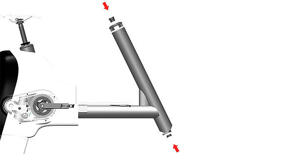
1.1 Remove Steering Fork Assembly with bearings
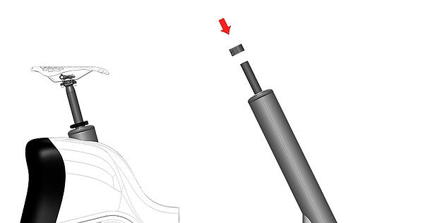
1.1 Loosen the Steering Tube Clamp screws and slide the clamp upwards to remove with a 4mm Hex Key.

1.2 Remove the Steering Fork Tube with bearings by pulling it downwards out of the frame. 
|
|
INFORMATION: Recover the Bottom Steering Fork Bush if it comes out with the Steering Tube. |

1.3 Remove the Top and Bottom Steering Tube Bushes and the Aero Frame End Cap if required.
3. Fit Steering Fork Assembly with bearings
TOOLS REQUIRED
| ID | Description | Task |
| M5 Hex Key | M5 Cap Screws - Steering Tube Clamp |
3.1 Press fit the Aero Frame End Cap to the Frame Steering Tube fit the Top and Bottom Steering Tube Bushes.
3.2 Insert the Steering Fork Assembly with Bearings into the Frame without dislodging the bushes.

|
|
CAUTION: Take care not to let the Stem slide down the Steering Tube to avoid the risk of the Stem scratching the coating on the Steering Tube. |
3.4 With the Fork Leg pointing forward, align and fasten the Steering Tube Clamp screws (2 x M6 Cap Screws) to a torque value of 5 Nm. [Hex Key: 5 mm]

4. Fit Handlebar & Stem Assembly
TOOLS REQUIRED
| ID | Description | Task |
| M4 Hex Key | M5 Cap Screws – Handlebar Stem |
4.1 With the Stem clamping screws loosened, slide the Handlebar Stem over the end of the Seat Tube.
4.2 Align the Handlebar & Stem Assembly with the Steering Fork Leg and fasten the screws to 4 Nm.

5. Fit Front Tiller Assembly to Steering Fork Leg
TOOLS REQUIRED
| ID | Description | Task |
| Hex Key 5 mm | Remove M8 Countersink Head Screw |
5.1 Push fit the M8 Nylock nut into its pocket on the Left-Hand side of the assembly.
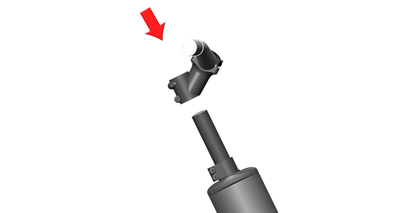
5.2 Push the Front Tiller Junction over the end of the Fork Leg so that the screw hole on tiller junction and fork leg align.
5.3 With the Front Tiller Assembly and Fork Leg Aligned, insert the M8 countersink head stainless steel screw with flat nylon washer to the Fork Leg to engage with the M8 Nylock nut.
5.4 Fasten the screw. Do not over tighten; torque to 4 Nm [Tools: 5mm Hex].